Routes
Basics
The anatomy of a route is crucial to understand:
1.1.1.0/24 via 10.0.0.1 eth0
A route is composed of two parts; what to match against and how to forward the matched packets. In the above example we want to match packets whose destination IP address is in the 1.1.1.0/24 subnet and then we want to forward those packet to 10.0.0.1 on interface eth0. We therefore want to match the prefix 1.1.1.0/24 and forward on the path to 10.0.0.1, eth0.
Matching on a prefix is the particular task of the IP FIB, matching on other packet attributes is done by other subsystems, e.g. matching on MPLS labels in the MPLS-FIB, or matching on a tuple in ACL based forwarding (ABF), ‘matching’ on all packets that arrive on an L3 interface (l3XC). Although these subsystems match on different properties, they share the infrastructure on how to forward matched packets, that is they share the paths. The FIB paths (or really the path-list) thus provide services to clients, this service is to contribute forwarding, this, in terms that will be made clear in later sections, is to provide the DPO to use.
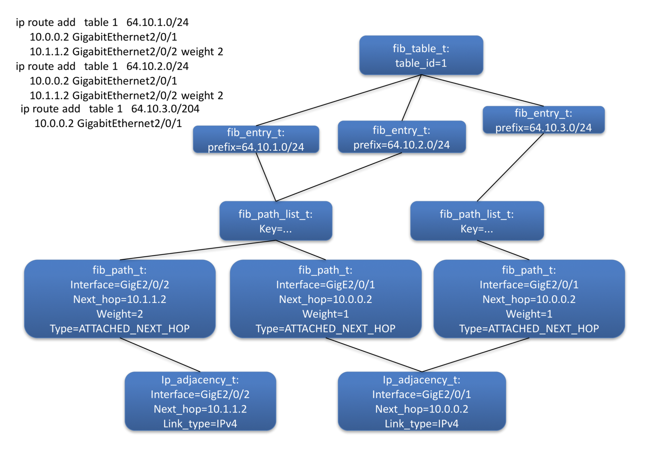
The prime function of the FIB is to resolve the paths for a route. To resolve a route is to construct an object graph that fully describes how to forward matching packets. This means that the graph must terminate with an object (the leaf node) that describes how to send a packet on an interface 1, i.e what encap to add to the packet and what interface to send it to; this is the purpose of the IP adjacency object. In Figure 3 the route is resolved as the graph is complete from fib_entry_t to ip_adjacency_t.
Thread Model
The FIB is not thread safe. All actions on the FIB are expected to occur exclusively in the main thread. However, the data-structures that FIB updates to add routes are thread safe, w.r.t. addition/deletion and read, therefore routes can be added without holding the worker thread barrier lock.
Tables
An IP FIB is a set of prefixes against which to match; it is sub-address family (SAFI) specific (i.e. there is one for ipv4 and ipv6, unicast and multicast). An IP Table is address family (AFI) specific (i.e. the ‘table’ includes the unicast and multicast FIB).
Each FIB is identified by the SAFI and instance number (the [pool] index), each table is identified by the AFI and ID. The table’s ID is assigned by the user when the table is constructed. Table ID 0 is reserved for the global/default table.
In most routing models a VRF is composed of an IPv4 and IPv6 table, however, VPP has no construct to model this association, it deals only with tables and FIBs.
A unicast FIB is comprised of two route data-bases; forwarding and non-forwarding. The forwarding data-base contains routes against which a packet will perform a longest prefix match (LPM) in the data-plane. The non-forwarding DB contains all the routes with which VPP has been programmed. Some of these routes may be unresolved, preventing their insertion into the forwarding DB. (see section: Adjacency source FIB entries).
Model
The route data is decomposed into three parts; entry, path-list and paths;
The fib_entry_t, which contains the route’s prefix, is the representation of that prefix’s entry in the FIB table.
The fib_path_t is a description of where to send the packets destined to the route’s prefix. There are several types of path, including:
Attached next-hop: the path is described with an interface and a next-hop. The next-hop is in the same sub-net as the router’s own address on that interface, hence the peer is considered to be attached
Attached: the path is described only by an interface. An attached path means that all addresses covered by the route’s prefix are on the same L2 segment to which that router’s interface is attached. This means it is possible to ARP for any address covered by the route’s prefix. If this is not the case then another device in that L2 segment needs to run proxy ARP. An attached path is really only appropriate for a point-to-point (P2P) interface where ARP is not required, i.e. a GRE tunnel. On a p2p interface, attached and attached-nexthop paths will resolve via a special ‘auto-adjacency’. This is an adjacency whose next-hop is the all zeros address and describes the only peer on the link.
Recursive: The path is described only via the next-hop and table-id.
De-aggregate: The path is described only via the special all zeros address and a table-id. This implies a subsequent lookup in the table should be performed.
There are other path types, please consult the code.
The fib_path_list_t represents the list of paths from which to choose when forwarding. A path-list is a shared object, i.e. it is the parent to multiple fib_entry_t children. In order to share any object type it is necessary for a child to search for an existing object matching its requirements. For this there must be a database. The key to the path-list database is a combined description of all of the paths it contains 2. Searching the path-list database is required with each route addition, so it is populated only with path-lists for which sharing will bring convergence benefits (see Section: Fast Convergence).

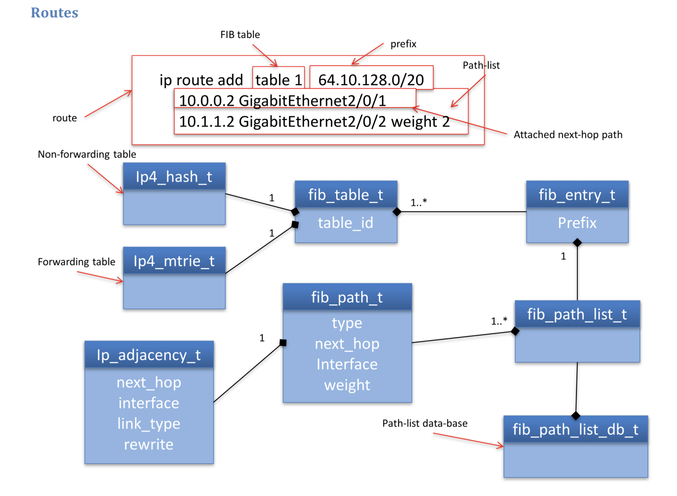
Figure 2: Route data model class diagram
Figure 2 shows an example of a route with two attached-next-hop paths. Each of these paths will resolve by finding the adjacency that matches the paths attributes, which are the same as the key for the adjacency database 3. The forwarding information (FI) is the set of adjacencies that are available for load-balancing the traffic in the data-plane. A path contributes an adjacency to the route’s forwarding information, the path-list contributes the full forwarding information for IP packets.

Figure 3: Route object diagram
Figure 3 shows the object instances and their relationships created in order to resolve the routes also shown. The graph nature of these relationships is evident; children are displayed at the top of the diagram, their parents below them. Forward walks are thus from top to bottom, back walks bottom to top. The diagram shows the objects that are shared, the path-list and adjacency. Sharing objects is critical to fast convergence (see section Fast Convergence).
FIB sources
There are various entities in the system that can add routes to the FIB tables. Each of these entities is termed a source. When the same prefix is added by different sources the FIB must arbitrate between them to determine which source will contribute the forwarding information. Since each source determines the forwarding information using different best path and loop prevention algorithms, it is not correct for the forwarding information of multiple sources to be combined. Instead the FIB must choose to use the forwarding information from only one source. This choice is based on a static priority assignment 4. The FIB must maintain the information each source has added so it can be restored should that source become the best source. VPP has two control-plane sources; the API and the CLI the API has the higher priority. Each source data is represented by a fib_entry_src_t object of which a fib_entry_t maintains a sorted vector.
The following configuration:
$ set interface ip address GigabitEthernet0/8/0 192.168.1.1/24
results in the addition of two FIB entries; 192.168.1.0/24 which is connected and attached, and 192.168.1.1/32 which is connected and local (a.k.a. receive or for-us). A prefix is connected when it is applied to a router’s interface. Both prefixes are interface sourced. The interface source has a high priority, so the accidental or nefarious addition of identical prefixes does not prevent the router from correctly forwarding. Packets matching a connected prefix will generate an ARP request for the packets destination address, this process is known as a glean.
An attached prefix also results in a glean, but the router does not have its own address in that sub-net. The following configuration will result in an attached route, which resolves via an attached path;
$ ip route add table X 10.10.10.0/24 via gre0
as mentioned before, these are only appropriate for point-to-point links.
If table X is not the table to which gre0 is bound, then this is the case of an attached export (see the section Attached Export).
Adjacency source FIB entries
Whenever an ARP entry is created it will source a fib_entry_t. In this case the route is of the form:
$ ip route add table X 10.0.0.1/32 via 10.0.0.1 GigabitEthernet0/8/0
This is a host prefix with a path whose next-hop address is the same host. This route highlights the distinction between the route’s prefix - a description of the traffic to match - and the path - a description of where to send the matched traffic. Table X is the same table to which the interface is bound. FIB entries that are sourced by adjacencies are termed adj-fibs. The priority of the adjacency source is lower than the API source, so the following configuration:
$ set interface address 192.168.1.1/24 GigabitEthernet0/8/0
$ ip arp 192.168.1.2 GigabitEthernet0/8/0 dead.dead.dead
$ ip route add 192.168.1.2 via 10.10.10.10 GigabitEthernet1/8/0
will forward traffic for 192.168.1.2 via GigabitEthernet1/8/0. That is the route added by the control plane is favoured over the adjacency discovered by ARP. The control plane, with its associated authentication, is considered the authoritative source. To counter the nefarious addition of adj-fibs, through the nefarious injection of adjacencies, the FIB is also required to ensure that only adj-fibs whose less specific covering prefix is attached are installed in forwarding. This requires the use of cover tracking, where a route maintains a dependency relationship with the route that is its less specific cover. When this cover changes (i.e. there is a new covering route) or the forwarding information of the cover is updated, then the covered route is notified. Adj-fibs that fail this cover check are not installed in the fib_table_t’s forwarding table, they are only present in the non-forwarding table.
Overlapping sub-nets are not supported, so no adj-fib has multiple paths. The control plane is expected to remove a prefix configured for an interface before the interface changes VRF.
Recursive Routes
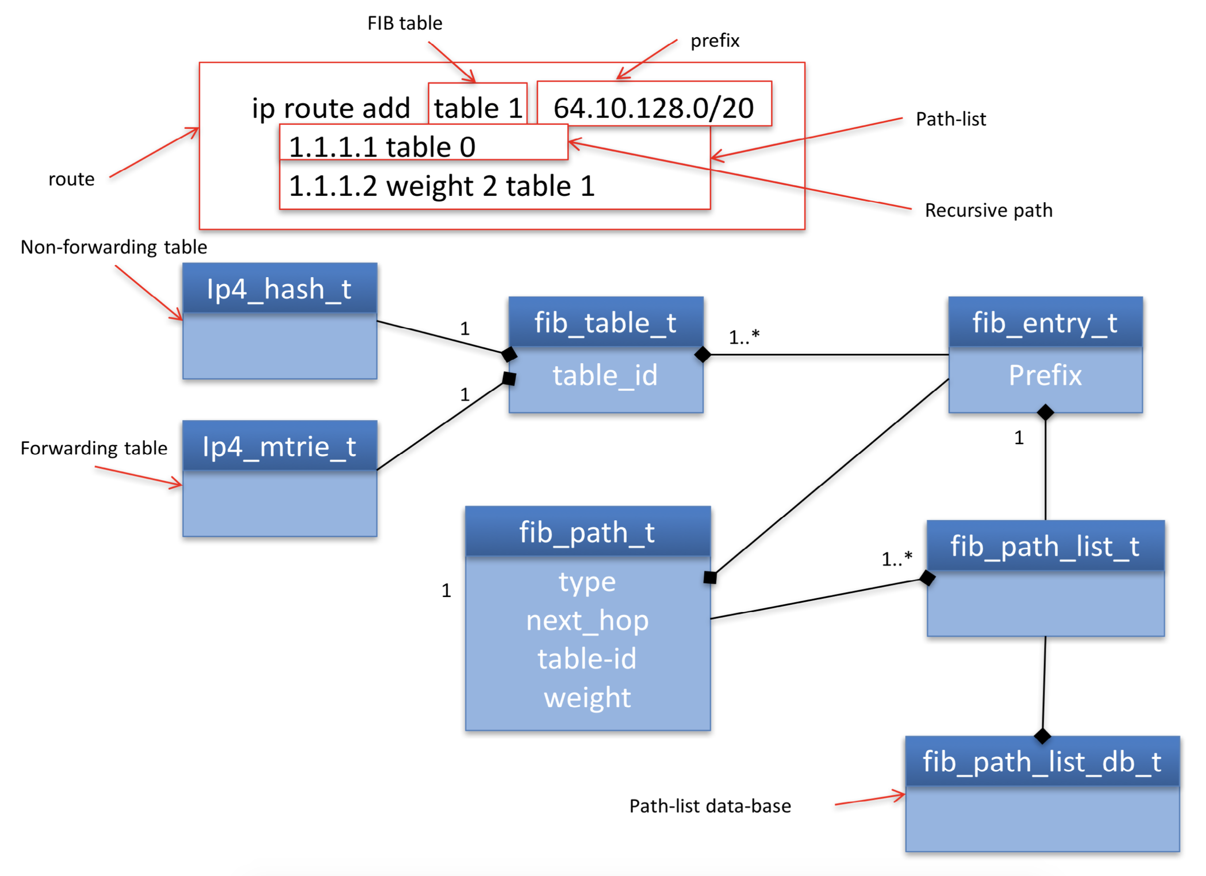
Figure 4 shows the data structures used to describe a recursive route. The representation is almost identical to attached next-hop paths. The difference being that the fib_path_t has a parent that is another fib_entry_t, termed the via-entry

Figure 4: Recursive route class diagram.
In order to forward traffic to 64.10.128.0/20 the FIB must first determine how to forward traffic to 1.1.1.1/32. This is recursive resolution. Recursive resolution, which is essentially a cache of the data-plane result, emulates a longest prefix match for the via-address” 1.1.1.1 in the *via-table table 0 5.
Recursive resolution (RR) will source a host-prefix entry in the via-table for the via-address. The RR source is a low priority source. In the unlikely 6 event that the RR source is the best source, then it must derive forwarding information from its covering prefix.
There are two cases to consider:
The cover is connected 7. The via-address is then an attached host and the RR source can resolve directly via the adjacency with the key {via-address, interface-of-connected-cover}
The cover is not connected 8. The RR source can directly inherit the forwarding information from its cover.
This dependency on the covering prefix means the RR source will track its cover The covering prefix will change when;
A more specific prefix is inserted. For this reason whenever an entry is inserted into a FIB table its cover must be found so that its covered dependents can be informed.
The existing cover is removed. The covered prefixes must form a new relationship with the next less specific.
The cover will be updated when the route for the covering prefix is modified. The cover tracking mechanism will provide the RR sourced entry with a notification in the event of a change or update of the cover, and the source can take the necessary action.
The RR sourced FIB entry becomes the parent of the fib_path_t and will contribute its forwarding information to that path, so that the child’s FIB entry can construct its own forwarding information.
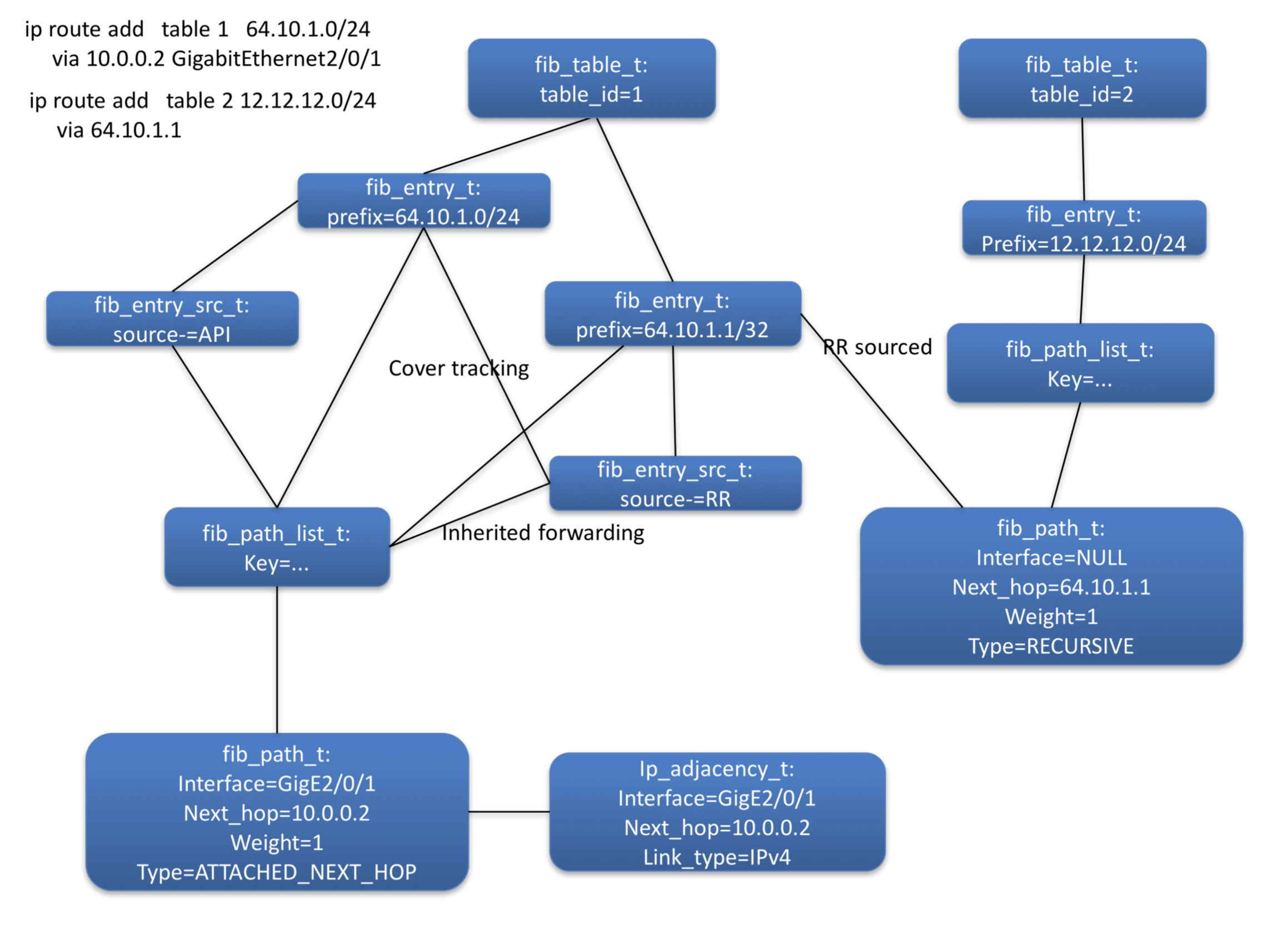
Figure 5 shows the object instances created to represent the recursive route and its resolving route also shown.

Figure 5: Recursive Routes object diagram
If the source adding recursive routes does not itself perform recursive resolution 9 then it is possible that the source may inadvertently programme a recursion loop.
An example of a recursion loop is the following configuration:
$ ip route add 5.5.5.5/32 via 6.6.6.6
$ ip route add 6.6.6.6/32 via 7.7.7.7
$ ip route add 7.7.7.7/32 via 5.5.5.5
This shows a loop over three levels, but any number is possible. FIB will detect recursion loops by forward walking the graph when a fib_entry_t forms a child-parent relationship with a fib_path_list_t. The walk checks to see if the same object instances are encountered. When a recursion loop is formed the control plane 10 graph becomes cyclic, thus allowing the child-parent dependencies to form. This is necessary so that when the loop breaks, the affected children and be updated.
Output labels
A route may have associated output MPLS labels 11. These are labels that are expected to be imposed on a packet as it is forwarded. It is important to note that an MPLS label is per-route and per-path, therefore, even though routes share paths they do not necessarily have the same label for that path 12. A label is therefore uniquely associated to a fib_entry_t and associated with one of the fib_path_t to which it forwards. MPLS labels are modelled via the generic concept of a path-extension. A fib_entry_t therefore has a vector of zero to many fib_path_ext_t objects to represent the labels with which it is configured.
Delegates
A common software development pattern, a delegate is a means to extend the functionality of one object through composition of another, these other objects are called delegates. Both fib_entry_t and ip_adjacency_t support extension via delegates.
The FIB uses delegates to add functionality when those functions are required by only a few objects instances rather than all of them, to save on memory. For example, building/contributing a load-balance object used to forward non-EOS MPLS traffic is only required for a fib_entry_t that corresponds to a BGP peer and that peer is advertising labeled route - there are only a few of these. See fib_entry_delegate.h for a full list of delegate types.
Tracking
A prime service FIB provides for other sub-system is the ability to ‘track’ the forwarding for a given next-hop. For example, a tunnel will want to know how to forward to its destination address. It can therefore request of the FIB to track this host-prefix and inform it when the forwarding for that prefix changes.
FIB tracking sources a host-prefix entry in the FIB using the ‘recusive resolution (RR)’ source, it exactly the same way that a recursive path does. If the entry did not previously exist, then the RR source will inherit (and track) forwarding from its covering prefix, therefore all packets that match this entry are forwarded in the same way as if the entry did not exist. The tunnel that is tracking this FIB entry will become a child dependent. The benefit to creating the entry, is that it now exists in the FIB node graph, so all actions that happen on its parents, are propagated to the host-prefix entry and consequently to the tunnel.
FIB provides a wrapper to the sourcing of the host-prefix using a delegate attached to the entry, and the entry is RR sourced only once. . The benefit of this approach is that each time a new client tracks the entry it doesn’t RR source it. When an entry is sourced all its children are updated. Thus, new clients tracking an entry is O(n^2). With the tracker as indirection, the entry is sourced only once.
Footnotes:
- 1
Or terminate in an object that transitions the packet out of the FIB domain, e.g. a drop.
- 2
Optimisations
- 3
Note it is valid for either interface to be bound to a different table than table 1
- 4
The engaged reader can see the full priority list in vnet/vnet/fib/fib_entry.h
- 5
Note it is only possible to add routes via an address (i.e. a/32 or /128) not via a shorter mask prefix. There is no use case for the latter
- 6
For iBGP the via-address is the loopback address of the peer PE, for eBGP it is the adj-fib for the CE
- 7
As is the case ofr eBGP
- 8
As is the case for iBGP
- 9
If that source is relying on FIB to perform recursive resolution, then there is no reason it should do so itself.
- 10
The derived data-plane graph MUST never be cyclic
- 11
Advertised, e.g. by LDP, SR or BGP
- 12
The only case where the labels will be the same is BGP VPNv4 label allocation per-VRF